Introduction
Expansion bellows are critical components in piping and heat exchanger systems, allowing for thermal expansion while minimizing stresses on connected equipment. Most bellows can be designed using hand calculations following EJMA standards, but complications arise when additional features, such as a drain piping penetration, are introduced into highly stressed areas.
In this project, we had to validate an expansion bellow design with a drain piping stub at the most critical location—the convolutions of the bellow. Since standard EJMA calculations were insufficient, and elastic analysis showed secondary bending stresses exceeding ASME VIII Div. 2, Part 5 limits, we turned to a detailed elastic-plastic finite element analysis (FEA) to ensure the structure would reach shakedown and avoid progressive plastic collapse.
Why Standard EJMA Calculations Were Insufficient
Typically, an expansion bellow without penetrations can be analyzed using EJMA formulas, which provide a reliable estimate of stress and fatigue life. However, the presence of a drain pipe stub in the bellow’s convolutions introduced significant local stress concentrations. A standard elastic analysis revealed that secondary bending stresses exceeded allowable limits, making it necessary to apply an elastic-plastic approach.
Design Considerations and Constraints
Several factors influenced the design and analysis:
- Material Selection: The bellow was made from austenitic stainless steel for its high corrosion resistance and flexibility.
- Operating Conditions: The system experienced pressure cycles (startup, shutdown, trip events) and temperature cycles (cold start, hot trip, and steady operation). These loading scenarios needed to be evaluated to determine potential ratcheting behavior.
- Complex Stress Distribution: The stub penetration in the convolutions caused significant local stress concentrations, which could not be captured accurately with hand calculations.
Finite Element Analysis (FEA) Approach
To accurately model the behavior of the bellow, SolidWorks Simulation was used for the elastic-plastic FEA. The model was set up as follows:
- Mixed Mesh Approach:
- The bellow was modeled using shell elements to capture its thin-walled nature efficiently.
- The area near the stub used solid elements to better resolve localized stresses and interactions.
- Boundary Conditions & Loading:
- Applied internal pressure and cyclic thermal loads corresponding to real-world operating conditions.
- Ensured realistic constraints that allowed for free expansion while simulating connections to adjacent structures.
- Material Modeling:
- The nonlinear material properties of austenitic stainless steel were incorporated to allow plastic deformation.
- Shakedown Assessment:
- Multiple load cycles were analyzed to determine if stresses would stabilize (shakedown) or lead to incremental plastic collapse.
Key Findings & Modifications
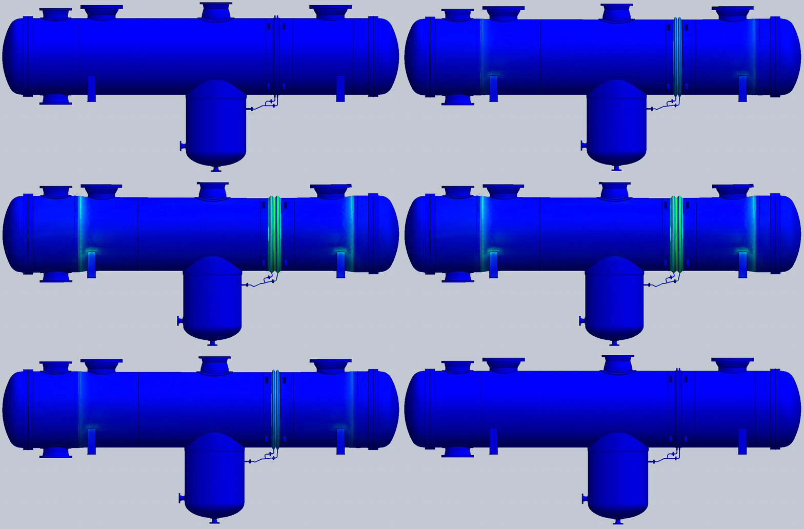
The FEA results showed that stresses initially exceeded yield limits, but over successive cycles, shakedown was achieved—indicating the bellow would remain structurally sound over its service life. However, some design modifications were necessary to optimize performance:
- Drain Piping Re-Routing: The stub’s original placement led to high stress concentrations, so the routing was adjusted to be more flexible, reducing the localized bending effects.
- Geometry Refinements: Small refinements were made to ensure the structure could withstand the full range of operating cycles without risk of plastic collapse.
Conclusion
This project highlighted the importance of elastic-plastic analysis in evaluating complex expansion bellow designs with non-standard features. While traditional EJMA methods or even elastic analysis can be sufficient in many cases, they are not always applicable when additional penetrations create localized stress concentrations. By leveraging FEA with an elastic-plastic approach, we were able to validate the design and ensure its long-term reliability under cyclic loading conditions.
The challenge was computationally intensive, with each simulation running for at least 8 hours on a desktop workstation, but the results provided the necessary confidence in the design. The approach taken in this case can serve as a valuable reference for future projects where standard analytical methods fall short due to geometric complexities and local stress effects.


