Introduction
Pipe stress analysis is crucial for ensuring the integrity and reliability of piping systems in various industrial applications, such as oil and gas, chemical processing, power generation, and water treatment plants. This analysis is essential to prevent failures due to excessive stress, fatigue, or deformation.
Piping systems consist of many components designed to form a pressure-tight system, including tees, elbows, weldolets, reducers, and more. Mainstream pipe stress analysis software simplifies these components by idealizing them as straight pipe beam elements. As a result, it does not account for the peak stresses caused by the structural discontinuities of piping components. These peak stresses can lead to fatigue failure under cyclic service.
It is therefore critical to adjust the stresses obtained from pipe stress analysis at nodes located at piping components using numerical stress intensification factors. These factors are developed through experimental testing or verified numerical analysis, such as Finite Element Analysis (FEA).
These stress intensification factors, known as SIFs, play a key role in accurately assessing the fatigue performance of piping systems. SIFs serve as multipliers applied to the nominal stress calculated for straight pipe sections, necessary at geometric discontinuities like bends and tees. They help estimate the maximum stresses and the potential for fatigue failure in piping components.
This article explores what stress intensification factors are, their importance, methods for determining them, and the role of the ASME B31J code.
What are Stress Intensification Factors (SIFs)?
Stress Intensification Factors (SIFs) are numerical factors used in pipe stress analysis to account for local stress concentrations due to geometry changes or discontinuities in piping systems . These concentrations typically occur at locations such as elbows, tees, branch connections, reducers, flanges, and welds. SIFs quantify the increase in stress at these locations compared to the nominal stress experienced by straight pipe segments under similar loading conditions . The American Society of Mechanical Engineers (ASME) defines SIFs as fatigue correlation factors used to compare the fatigue life of piping components to that of girth butt welds in straight pipe under bending moments.57 The SIF for a girth butt weld is defined as 1.0.
The concept of SIF was first introduced by A.R.C. Markl and colleagues in the 1950s through extensive fatigue testing . Markl defined SIF as the ratio of the peak stress at a component to the nominal stress in a similar, straight pipe :
SIF = Actual Stress at Discontinuity divided by the Nominal Stress in Straight Pipe.
Markl’s work involved cyclic moment loading tests on various piping components, primarily using 4-inch nominal diameter, Schedule 40 carbon steel piping. While his research was groundbreaking, it had limitations, including a focus on size-on-size fittings and the omission of configurations like reduced outlet tees, which can lead to inaccuracies. His formulas also did not explicitly account for torsional stress intensification.
SIF values typically exceed unity, indicating higher stresses at discontinuities or geometry changes.
Why Use Stress Intensification Factors?
I. Accurate Stress Prediction
Piping systems experience various loads, including pressure, thermal expansion, seismic forces, weight, and fluid dynamics. Without considering SIFs, stresses might be underestimated, potentially causing unexpected failures. SIFs allow engineers to identify high-stress areas, prompting necessary design adjustments.
The relationship often used in pipe stress analysis is: (Beam stress) · (SIF) ≤ Allowable Stress .
II. Importance of Using SIFs:
- Safety Assurance: Identifying potential weak points reduces risks of catastrophic failure.
- Compliance with Codes: Codes like ASME B31.1 , B31.3 , and others require SIF application.
- Enhanced Reliability: Early identification of high-stress areas improves system reliability and lifespan.
- Cost Savings: Proper stress evaluation prevents costly repairs and operational downtime.
III. The Role of ASME B31J
Traditionally, SIFs were listed explicitly in piping codes like ASME B31.3. However, recent updates have shifted the methodology for calculating these factors to ASME B31J , which provides standardized methods to calculate SIFs for various piping components using more precise equations based on finite element analysis . ASME B31J offers a consistent approach for determining SIFs, flexibility factors, and sustained stress multipliers for standard, non-standard, and proprietary fittings.
ASME B31J significantly enhances accuracy and consistency compared to previous code-based SIF calculations . It outlines methods like physical testing and virtual testing using Finite Element Method (FEM) analysis to obtain SIFs, especially for geometries not covered by earlier B31 codes.
ASME B31.3 now references B31J , recommending its use for calculating SIFs instead of older tabulated or simplified equations. The 2020 editions (and later) of ASME B31.1 and B31.3 mandate or heavily recommend the use of B31J, with B31.3-2020 removing Appendix D, which previously contained SIFs.
This transition ensures a more accurate stress analysis aligning closely with modern computational methods.
How and Where Do You Find SIFs?
SIF values can be derived from:
I. ASME B31J Code
ASME B31J provides standardized methods and equations for determining SIFs for piping components :
-
- Elbows: Based on radius, thickness, and bend angle.
- Tees and Branches: Defined by geometry and loading conditions. B31J provides separate SIFs for the header and branch, offering more accuracy than previous codes.
- Reducers and Expansions: Determined by geometry ratios and transitions.
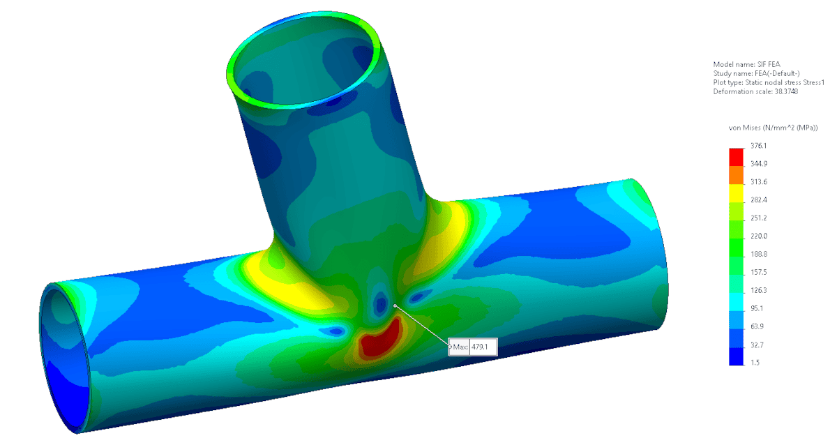
II. Finite Element Analysis (FEA)
FEA tools like ANSYS, Abaqus, or SolidWorks Simulation can numerically calculate accurate SIF values, particularly useful for complex or unique fittings not covered explicitly in codes . FEA involves creating a virtual model, applying loads and boundary conditions, and calculating the stress distribution to determine the SIF by comparing peak stresses to nominal stresses. ASME B31J recognizes FEA as a valid method, especially for larger diameter pipes.
III. Experimental Testing
Historically significant, testing involves strain gauges and cyclic fatigue testing for unique or novel configurations, providing empirical validation for SIF values . ASME B31J includes a nonmandatory appendix (Appendix A) outlining a standard experimental method for developing SIFs. While providing direct empirical data, it can be time-consuming and expensive.
Practical Application of SIFs in Pipe Stress Analysis
Pipe stress software (CAESAR II , AutoPIPE , ROHR2 2, PASS/START-PROF ) integrates SIF values into analysis, enhancing stress prediction accuracy . These software packages often have ASME B31J directly incorporated, allowing users to easily apply the standard’s SIF and flexibility factor calculations . Engineers input specific geometry and use B31J-derived or FEA-derived SIF values to evaluate stresses, highlighting critical areas needing further assessment. For non-standard fittings, users can often manually input custom SIF values obtained from FEA or testing. For example, in CAESAR II, SIFs are applied at node points representing fittings, with users able to input in-plane and out-of-plane SIFs based on the fitting type and loading direction.
Limitations of Standard SIF Values
- Overgeneralization: Standard code SIF values may not accurately reflect complex piping configurations or non-standard fittings, especially those with high diameter-to-thickness ratios or geometries not covered in original testing. For instance, tees with a D/t ratio exceeding 100 or fittings not part of Markl’s original tests may not be accurately assessed.
- Conservatism: Standard values tend to be conservative; FEA-derived values can result in more economical designs. However, in some cases, standard SIFs can be non-conservative, underestimating stresses, particularly in configurations like reduced outlet tees.
- Limited Scope: Markl’s original tests primarily involved 4-inch nominal diameter piping and size-on-size fittings, which might not be directly applicable to significantly different sizes or configurations. Standard SIFs have also historically focused on moment loadings and may not fully account for torsional or axial forces.
Best Practices for Using SIFs:
- Follow ASME B31J recommendations for SIF calculations .
- Validate code-based SIFs with detailed FEA for critical applications or non-standard geometries .
- Regularly update and verify software inputs to reflect accurate SIF data.
- Adhere to all applicable piping codes and standards.
- Create detailed and accurate piping system models in stress analysis software
- Define all relevant operating conditions and load cases.
- Select and apply the correct SIF values for each component, considering in-plane, out-of-plane, and torsional factors.
- Consider the flexibility of piping components using appropriate flexibility factors (k-factors) from codes or B31J.
- Thoroughly review and validate analysis results against allowable limits.
Conclusion
Stress Intensification Factors (SIFs) are essential for accurate pipe stress analysis, significantly influencing safety, compliance, and operational reliability. The adoption of ASME B31J enhances precision in determining these factors, aligning industry practice with advanced computational and experimental methods . Engineers must judiciously select, calculate, and apply SIFs to ensure robust and compliant piping system designs.
References
- ASME B31J-2017, “Standard for Determining Stress Intensification Factors (i-Factors) for Metallic Piping Components,” The American Society of Mechanical Engineers, New York, NY, 2017.
- ASME B31.3-2020, “Process Piping,” The American Society of Mechanical Engineers, New York, NY, 2020.
- ASME B31.1-2020, “Power Piping,” The American Society of Mechanical Engineers, New York, NY, 2020.
- Woods, G.E., Baguley, N., Practical Guide to ASME B31.3 – Process Piping, CASTI Publishing, Alberta, Canada, 2016.
- Kannappan, S., Introduction to Pipe Stress Analysis, Wiley, 1986.
- Peng, L.C., and Peng, T.L., Pipe Stress Engineering, ASME Press, 2009.
- Nayyar, M., Piping Handbook, 7th Edition, McGraw-Hill Education, 1999.
- “Piping-Flexibility Analysis” by A.R.C. Markl, ASME Paper 53-A-51.
- “Experimental Evaluation of the Markl Fatigue Methods and ASME Piping Stress Intensification Factors” paper coauthored by Tony Paulin and Chris Hinnant.
- WRC Bulletin 463, “Report 1: Standardized Method for Developing Flexibility Factors for Piping Components,” E. C. Rodabaugh and E. A. Wais (July 2001).