
Background
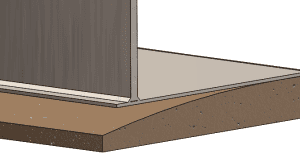
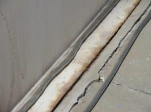
Edge settlement in aboveground storage tanks occurs when the soil or foundation beneath the tank shell deforms or erodes. This causes the outer portion of the tank bottom to sag, especially near the shell-to-bottom junction — a highly stressed and fatigue-sensitive region.
API 653 Appendix B provides quantitative acceptance criteria for evaluating such edge settlement. These criteria are based on the radius of the settled area (R) and whether the bottom weld seams are parallel or perpendicular to the shell.
Originally, API 653 used the B = 0.37·R rule as a conservative screening line. Later revisions introduced empirically validated and FEA-supported curved acceptance lines that vary with tank diameter and weld orientation. These reflect realistic stress behavior and are less conservative than the original slope-based criterion.
Typical consequences of edge settlement, as confirmed by industry case studies and FEA, include inward shift of the hinge point, plastic deformation of the bottom plate, and increased risk of cracking at the shell-to-bottom weld — often leading to leakage, particularly when combined with corrosion or brittle material behavior.
Importantly:
- API 653 allows a minimum of 2 inches of settlement in all cases.
- If measured edge settlement exceeds 75% of the allowable B<sub>ew</sub>, the area must undergo non-destructive examination (NDE) using magnetic particle or liquid penetrant methods.
- For cases that exceed the allowable curve entirely, further assessment — often via Level 2 or 3 Fitness-For-Service (FFS) analysis per API 579 — is required.
Case Summary: Edge Settlement Beyond 75% Threshold
We recently assessed a vertical steel storage tank where measured settlement at the shell edge exceeded 75% of the allowable value based on API 653 Figure B-10. The vertical displacement was approximately 50 mm (2 inches), with a short settlement radius — making it a sharp, localized dip.
Rather than proceed directly to repair or replacement, we conducted a nonlinear finite element analysis (FEA) to evaluate:
- The resulting stress distribution near the shell-bottom junction,
- The shift in hinge point location of the bottom plate,
- The potential for ratcheting or fatigue failure under cyclic loading.
Modelling Approach
We created two comparative models in [SolidWorks Simulation / your software]:
- Perfect foundation (no deformation),
- Edge-settled foundation, with 50 mm localized vertical drop at the shell edge.
Key modelling features:
- Shell and bottom plate modeled with correct thicknesses and material properties.
- Fillet weld region included.
- Contact interaction modeled to simulate loss of support under the bottom plate.
- Operating pressure applied to simulate normal tank fill.
- Deformation results scaled for visualization.
Simulation Results
- Perfect Foundation


- Bottom plate remains fully supported.
- The hinge point — where the plate rotation initiates — aligns with the outer edge of the bottom plate.
- Stresses are low and broadly distributed, with minimal distortion at the shell-to-floor junction.
- Edge Settlement: 50 mm


- The plate sags downward into the unsupported region.
- The hinge point shifts inward, closer to the shell.
- von Mises stress increases significantly in the floor plate and weld toe area due to bending concentration.
- The change in curvature suggests higher strain demands on the material in a very localized zone.
- Comparison between the linear elastic analysis and the elastic plastic (non-linear) analysis can be seen in the above two motion stress plot.
Interpretation with API 653 Context
Our results validate the structural reasoning behind API 653 Appendix B:
- With localized edge settlement, the plate no longer bends at the free edge but rather at a point closer to the shell, amplifying stresses in the weld and plate.
- This inward hinge shift and stress amplification match the observations used to develop the modern acceptance curves.
- The old B = 0.37·R rule would have flagged many acceptable tanks unnecessarily — our FEA confirms why API transitioned to the current limit curves.
In our analysis, the von Mises stress exceeded the material’s yield strength, confirming localized plasticity. However:
- The stress remained below 2×Sy, meeting the non-ratcheting requirement per API 579.
- The cyclic stress range was below the low-cycle fatigue limit, indicating acceptable fatigue life even with yield onset.
This confirms that the tank is not at risk of ratcheting or fatigue crack growth, and the plastic strain is self-limiting under expected loading cycles.
Engineering Takeaway
Edge settlement does not automatically mean the tank must be repaired — but it does warrant a technical assessment.
Our nonlinear FEA with contact modelling:
- Revealed how stress and hinge location change dramatically once the 2-inch settlement threshold is reached,
- Confirmed that plastic deformation is localized and structurally tolerable under current operating conditions,
- And provided a code-compliant justification for continued operation without repair.
The insights here are consistent with how the API 653 task group originally developed the settlement curves — combining field experience with detailed simulation.