
Designing and verifying industrial piping systems demands both precision and structure. At SimuMech, our engineers follow a disciplined, end-to-end workflow using CAESAR II to ensure that every system is safe, code-compliant, and buildable.
Below is a detailed look at the full process — from project intake to final hand-over.
Phase 1 — Intake, Scoping & Set-Up
A successful stress analysis begins long before any modelling starts.
1.1 Collect Minimum Project Inputs
We gather all essential information:
- Project specifications, code basis, and company standards
- Piping line list with pressures, temperatures, fluid properties, corrosion allowance, and insulation
- P&IDs, isometrics, pipe class sheets, and in-line equipment data
- Equipment Vendor drawings (nozzle allowables, thermal growth, alignment targets)
- Layout models for structures and equipment
- Environmental loading (wind, seismic, snow) and construction/test requirements
1.2 Understand Constraints & Interfaces
We identify which items drive the design — critical equipment, structural tie-ins, operational access, fabrication limits — to ensure the stress model mirrors the physical plant.
1.3 Define the Analysis Scope
Not every line needs full analysis. We prioritise:
- Safety-critical, high-temperature or rotating-equipment lines
- Long runs or vibration-prone systems
- Flare, relief, or buried yard piping
See our detailed post outlining the full criteria: When to perform a detailed pipe stress analysis
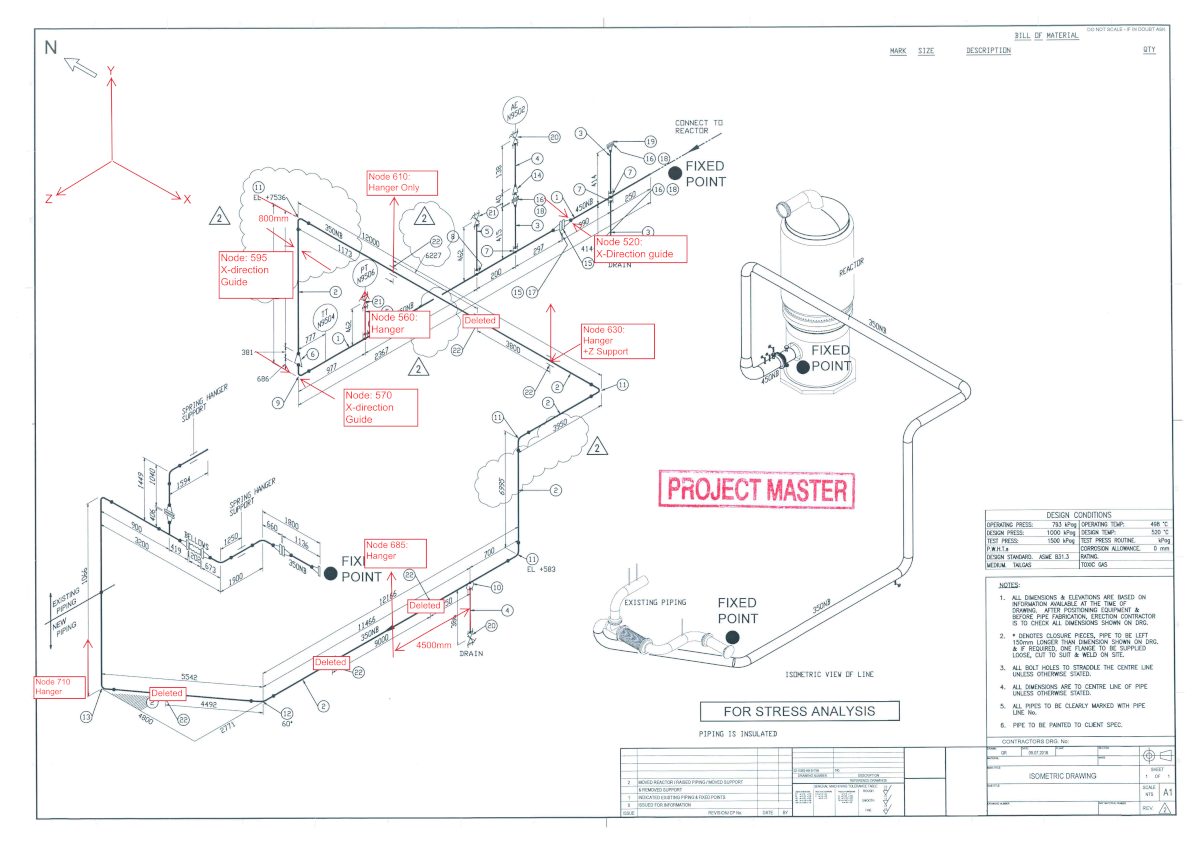
1.4 Mark-Up Isometrics
Before modelling, we red-line isometrics to fill in missing dimensions, assign node numbers and record component weights (valves, flanges, actuators, inline equipment).
1.5 Choose the Model-Build Method
Depending on the data quality, we import PCF files or build manually using supplied Isometric drawings or 3d models. Node numbering, naming conventions, and battery limits are fixed at this stage to keep revisions manageable.
Phase 2 — Modeling & First Run
2.1 Set Project Options
Code edition, materials, corrosion allowance, and default friction/gap values are locked in.
2.2 Build Geometry
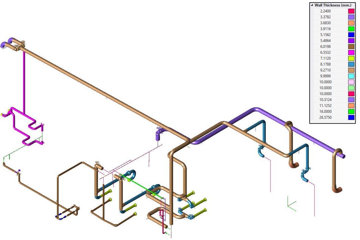
Model all elbows, reducers, tees, and rigid elements (Flanges, valves etc.) to scale, ensuring correct wall thicknesses and material densities. Apply line numbering during modelling and assign descriptive names to key nodes, such as equipment connection points.
2.3 Apply Realistic Supports
Guides, line stops, and anchors are positioned for realistic stiffness and thermal flexibility — not idealised perfection. Springs are inserted where movement requires load balancing.
2.4 Apply Loads and Temperatures
Weights, pressures, metal temperatures, imposed displacements, and any occasional loads are entered explicitly. Buried pipe segments use soil springs where needed.
2.5 Assemble Load Cases
We construct the static editor matrix (SUS, OPE, EXP, OCC, HYDRO) to capture all conditions consistently.
2.6 First Run
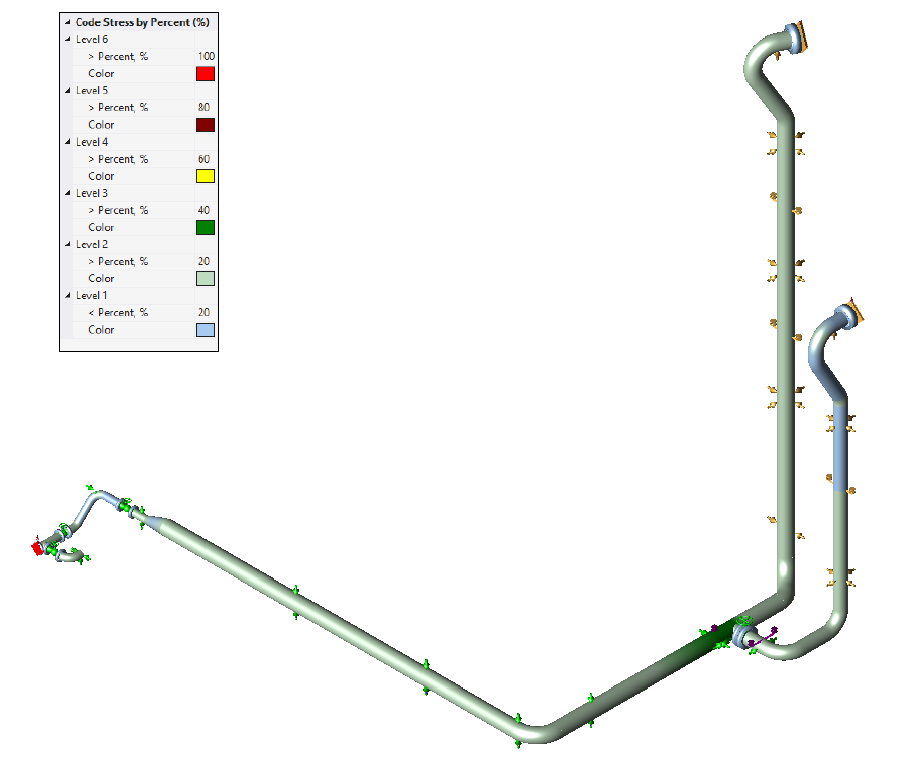
We correct disconnected nodes or illegal restraints, then review displacements, support reactions, and preliminary code stresses before redesigning/optimisation.
Phase 3 — Iteration: Compliance & Buildability
Thermal growth paths are tuned by adjusting stops, gaps, and friction. Expansion loops or bellows are added where necessary.
3.1 Design and Tune Springs
CAESAR’s Hanger Design module finalises variable or constant spring data. All relevant load cases are regenerated.
3.2 Verify Equipment Nozzle Loads
We check each nozzle against vendor allowables (API 610, NEMA SM-23, etc.). If overstressed, we modify flexibility or support layout.
3.3 Handle Occasional Loads
Wind and seismic load cases are run per project criteria, ensuring supports and structures can withstand lateral events.
3.4 Include Dynamics (When Required)
For relief, slug, or machinery-induced vibration, we perform transient or harmonic response studies using credible damping ratios.
3.5 Check Flange Tightness
Where leakage control is critical, we perform detailed flange analysis.
Phase 4 — Close-Out & Handover
4.1 Redline Stress Isometrics
Final mark-ups include support and equipment connection node numbers, all modifications made (Expansion loops, new support location etc.), added support details, and information on springs and bellows.
4.2 Compile the Deliverables Pack
We issue a concise, client-friendly report containing:
- Assumptions, options, and code settings
- Model overview and boundaries
- Stress compliance summaries
- Nozzle-load comparison tables
- Flanged Leak Check
- Support reactions for structural design
- Displacement and spring schedules
Learn more in our post on what to include in a comprehensive pipe stress analysis report: What to include in a comprehensive pipe stress report
4.3 Management of Change (MOC)
Any layout or design modification triggers controlled re-analysis and updated deliverables with recorded deltas.
Conclusion
An effective pipe stress workflow is as much about discipline and communication as it is about analysis. By following this structured process, SimuMech ensures every CAESAR II model leads to practical, safe, and code-compliant designs — from the first ISO markup to final sign-off.